Description
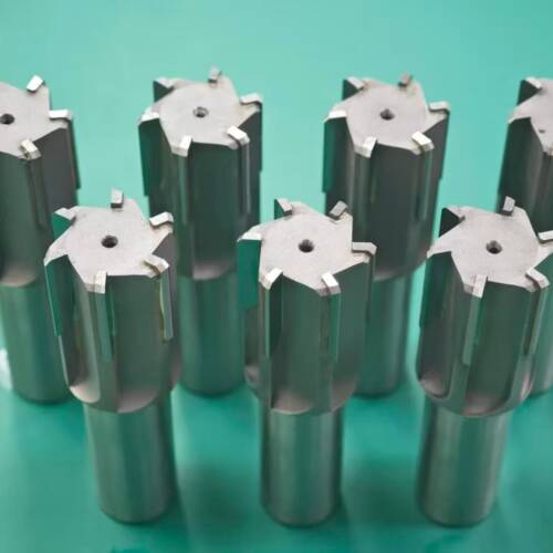
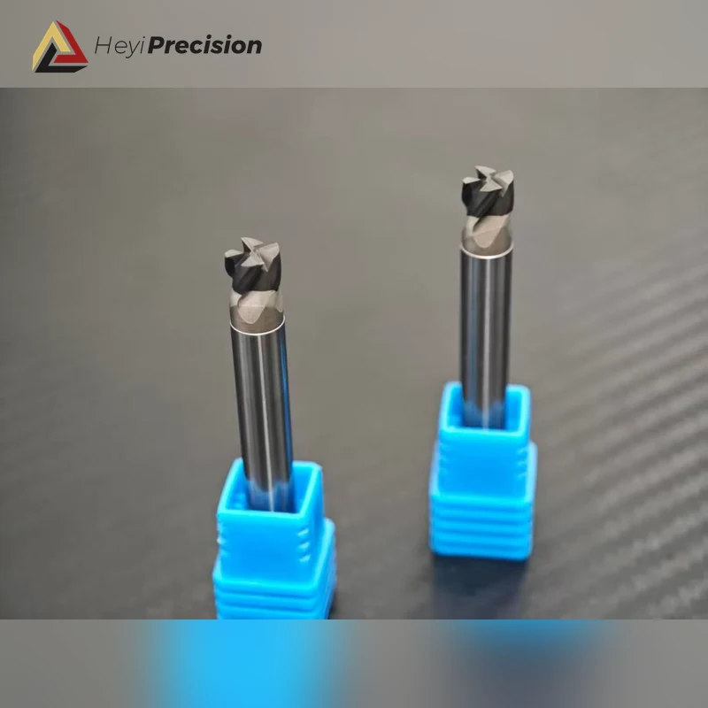
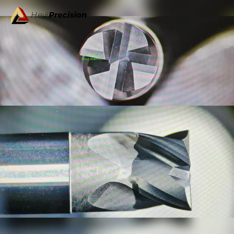
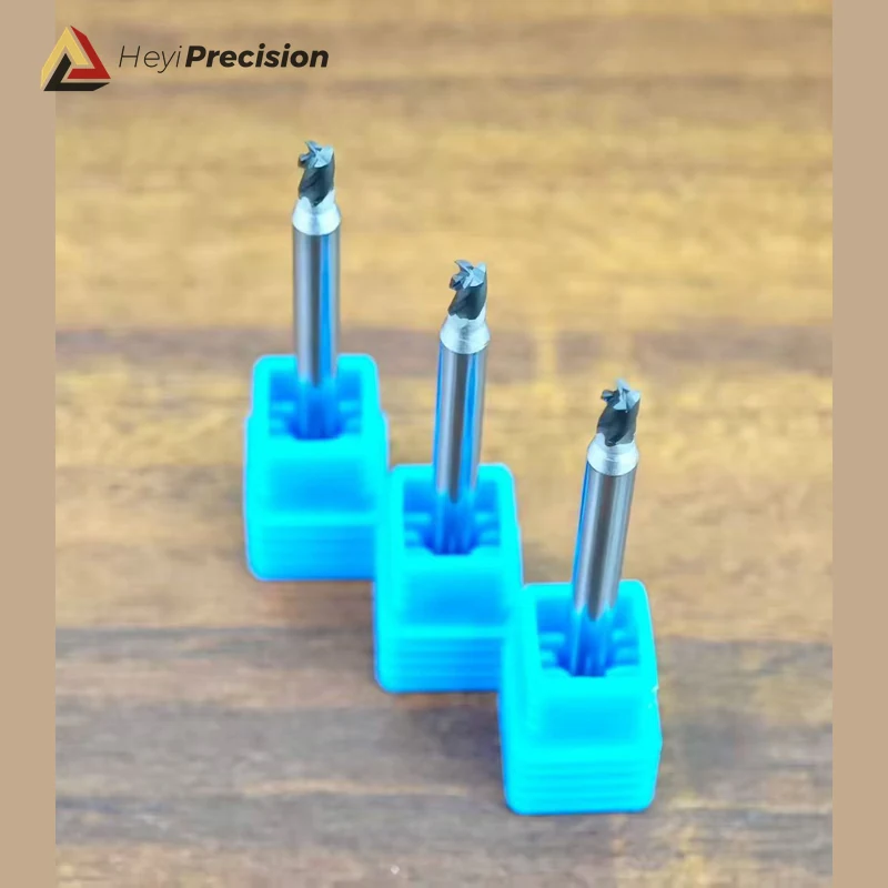
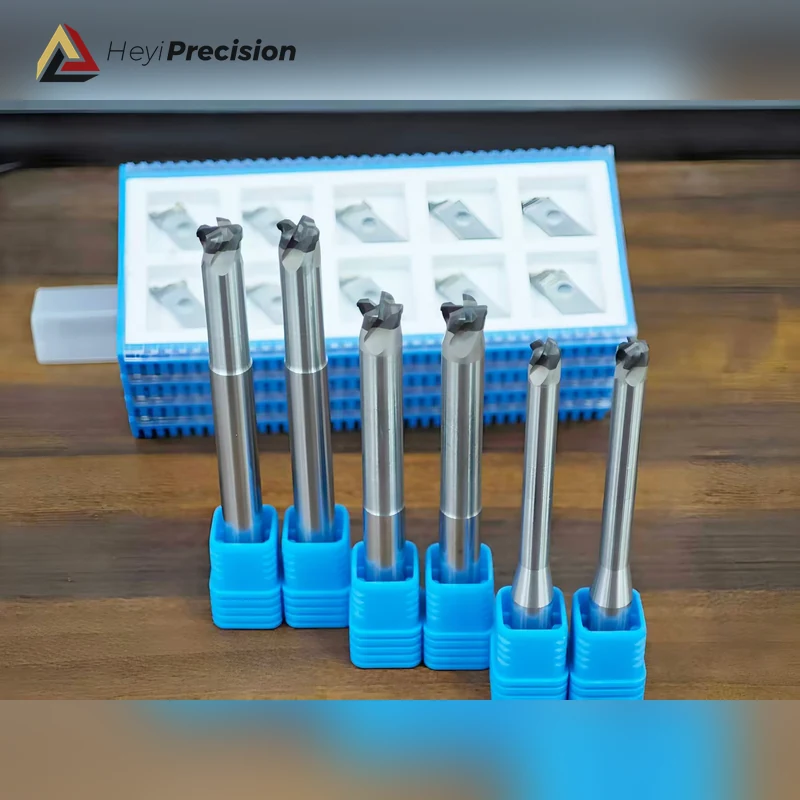
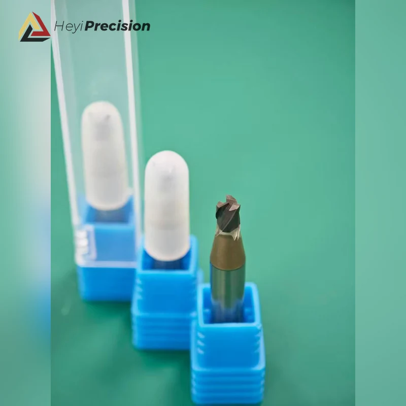
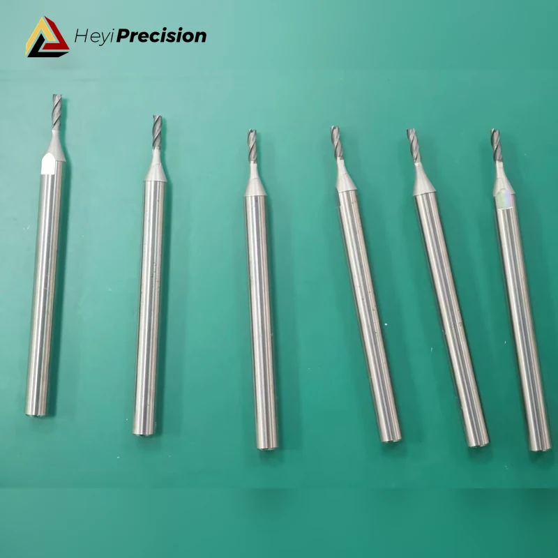
A solid PCD milling cutter is a custom rotary tool with an integral polycrystalline diamond cutting head for high-speed precision milling of aluminum, high-silicon aluminum, copper alloys, graphite, CFRP, and other abrasive non-ferrous or composite materials. It is selected when edge consistency, low runout, wear stability, and a clean machined surface are more important than using a general-purpose indexable cutter.
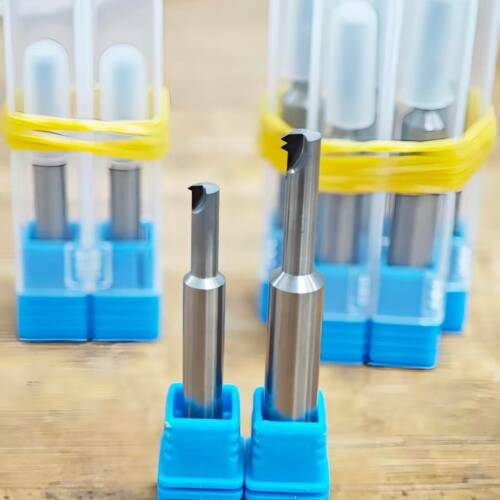
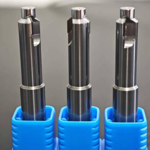
Unlike a cutter assembled with separate brazed PCD tips, this design uses a one-piece PCD cutting section. The flute form, cutting diameter, neck, corner geometry, and shank are produced around the customer’s operation. Final tool geometry and cutting parameters must be confirmed from the workpiece, machine, holder, tolerance, and surface-finish requirement.
Where a solid PCD milling cutter fits
| Workpiece or operation | Typical reason to use PCD | Application note |
|---|---|---|
| Aluminum and high-silicon aluminum | Wear resistance with a sharp edge for stable dimensions and finishing | Share silicon content, allowance, coolant method, and required surface finish. |
| Copper and other non-ferrous alloys | Clean cutting and controlled edge geometry | Confirm burr limits, wall thickness, and whether the cut is interrupted. |
| Graphite | Resistance to abrasive wear during dry machining | Dust extraction, machine protection, and edge design must be reviewed. |
| CFRP, GFRP, and abrasive composites | Edge retention for trimming, slotting, and profile work | Provide laminate, fiber direction, thickness, and delamination or burr limits. |
| Shoulder, slot, pocket, and profile milling | A dedicated form can combine access, finish, and tool-life requirements | Send the toolpath, engagement, reach, and collision restrictions. |
Why use an integral PCD cutting head?
- Consistent cutting geometry: the cutting section can be produced as one controlled form instead of positioning several separate tips.
- Wear stability: PCD is suited to abrasive non-ferrous and composite work where carbide edge wear can change dimensions or surface finish too quickly.
- Compact custom profiles: flute count, neck clearance, reach, corner form, and cutting length can be matched to a restricted toolpath.
- Finish-oriented edge preparation: edge sharpness and corner geometry can be selected for burr control, dimensional stability, or a finishing pass.
These advantages depend on the complete setup. Spindle condition, holder runout, workholding, chip or dust evacuation, tool overhang, and cutting data can affect the result as much as the cutter material.
Custom geometry options
HEYI reviews each solid PCD milling cutter as an application-specific tool. Common design inputs include:
- cutting diameter, cutting length, and overall length;
- flute count, helix direction, and chip-space requirement;
- sharp corner, chamfer, corner radius, or form profile;
- neck diameter, reach, taper, and interference clearance;
- straight shank or application-specific connection;
- internal coolant or external coolant strategy where appropriate;
- balance, runout, tolerance, and surface-finish targets.
Material and process limitations
PCD is generally not the first choice for steel, hardened steel, stainless steel, or other ferrous materials at normal cutting temperatures. For those workpieces, a carbide or CBN solution may be more appropriate. PCD also does not correct an unstable spindle, excessive holder runout, poor workholding, or inadequate chip evacuation.
For abrasive composites, share the laminate structure and acceptance criteria before tool design. For graphite, include the dust-control arrangement. Trial quantities or a staged application review may be appropriate when the material or toolpath is new.
Information needed for quotation
For a useful engineering review, send the following:
- part drawing, tool drawing, or 3D model;
- workpiece material and grade, including silicon content or composite layup when relevant;
- operation type, radial and axial engagement, and machining allowance;
- machine, spindle speed range, holder interface, and coolant or dust-extraction method;
- required tolerance, edge condition, and surface finish;
- current tool, tool-life issue, cycle-time target, and expected quantity.
Send the full RFQ and upload your drawing, or contact HEYI for an initial application review. You can also compare the wider PCD tool range and solid PCD end mills for aluminum and composites.
Frequently asked questions
What materials can a solid PCD milling cutter machine?
Typical applications include aluminum, high-silicon aluminum, copper alloys, graphite, CFRP, GFRP, and other abrasive non-ferrous or composite materials. The exact edge geometry and PCD grade depend on the material and operation.
Is this cutter suitable for steel?
Normally no. Diamond cutting tools are generally avoided for ferrous materials at normal cutting temperatures. Send the material grade and hardness so HEYI can review a carbide or CBN alternative.
What is the difference between solid PCD and brazed PCD cutters?
A solid PCD cutter uses an integral PCD cutting section, while a brazed PCD cutter uses separate PCD tips joined to a tool body. The better choice depends on diameter, profile complexity, cutting load, repair strategy, and total tooling cost.
Can HEYI recommend cutting parameters?
Yes, after the tool geometry and application are confirmed. Recommended starting data must consider the workpiece, cutter diameter, flute count, engagement, machine, holder, coolant or dust extraction, and target finish.
Quick Product Inquiry
Ask about tooling, lead time, or application fit. We will reply with a tailored recommendation.
Need to upload drawings or full machining data? Use Full RFQ