


PCD Micro Drilling and Finishing
PCD Micro Drill and End Mill for Aluminum/Fiberglass and CVD SiC
Use this application route when a part needs small-diameter holes and clean profile finishing in aluminum/fiberglass composites, CVD SiC, graphite, ceramics, or similarly abrasive hard-brittle materials.
When this solution fits
The practical route is to use a solid PCD micro drill for small holes and a solid PCD end mill for edge or profile finishing when abrasive material wear and edge chipping are the main problems. The final geometry and cutting window still need to match the real workpiece, machine, runout, hole size, hole depth, and acceptable chipping limit.
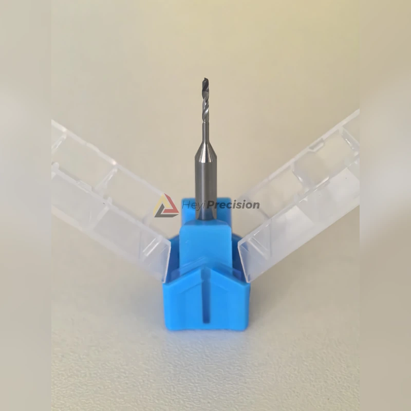
- Aluminum/fiberglass composite parts where aluminum burrs and fiberglass fraying appear in the same component.
- CVD SiC, ceramics, graphite, CFRP/GFRP, and other abrasive or hard-brittle workpieces.
- Micro-hole drilling where D0.5, D1.0, or customized small-diameter holes require stable entry and exit edges.
- Profile finishing where carbide tools wear too quickly or leave unstable edge quality across a batch.
Main machining problems
Fast edge wear
Fiberglass, SiC, graphite, and ceramic materials are abrasive. Once a cutting edge becomes dull, the process shifts from shearing to pushing, rubbing, or tearing the material.
Hole-edge breakout
Micro drilling is sensitive to runout, point geometry, clamping, and chip evacuation. Even small vibration can show as burrs, scratches, or chipping.
Frayed composite layers
In aluminum/fiberglass stacks, the aluminum side and fiberglass layer do not cut the same way, so tool sharpness and edge retention matter more than speed alone.
Unstable batch quality
A tool that works on the first parts is not enough. The real question is whether hole and edge quality stay stable as the cutting edge wears.
Recommended tooling route
The solid PCD micro drill is the starting point for small-diameter holes in abrasive or hard-brittle materials. A stable PCD cutting edge can help maintain hole quality under suitable machine, clamping, and chip-evacuation conditions.
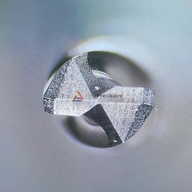
For the profile or edge-finishing operation, solid PCD end mills are a better match than general-purpose tooling when the workpiece is non-ferrous, abrasive, or composite-based. They are used to keep the cutting action sharp rather than letting a rounded edge tear or chip the material.
RFQ data needed
- Workpiece material: aluminum/fiberglass, CVD SiC, ceramic, graphite, CFRP/GFRP, or other composite material.
- Hole diameter, hole depth, tolerance, material thickness, stack structure, and edge-quality requirement.
- Milling profile, slot width, cutting depth, tool overhang, and current tool type.
- Photos of burrs, chipping, delamination, micro-cracks, rough finish, or other defects.
- Machine model, spindle speed range, runout condition, coolant or air-blast method, and current cutting data.
PCD Micro Drills for SiC, Quartz, and Ceramic Small Holes
Small holes in SiC, quartz, ceramic, and similar hard-brittle materials need a different review from ordinary metal drilling. Exit chipping, edge breakout, runout marks, and micro-cracks can make the hole unacceptable even when the diameter is close to target.
HEYI reviews the material and hole condition before recommending a solid PCD micro drill. Important details include hole diameter, hole depth, wall thickness, entry support, exit support, spindle runout, and whether the hole is inspected visually, dimensionally, or by edge-quality limit.
- Is the material abrasive, brittle, or both?
- Is the hole through, blind, angled, or close to an unsupported edge?
- What amount of exit chipping is acceptable, if any?
For RFQ review, send the material name, drawing, hole diameter, depth, tolerance, chipping limit, current tool, machine model, spindle runout condition, and photos of existing hole defects.
Can one PCD micro drill cover SiC, quartz, and ceramic materials?
Not automatically. These materials are all hard or brittle, but their cutting behavior is different. HEYI needs the material grade, hole size, edge-quality requirement, and machine condition before confirming drill geometry.
What causes exit chipping in hard-brittle micro drilling?
Common causes include poor exit support, excessive runout, unstable feed, dull cutting edges, weak clamping, and a drill geometry that does not match the material.