


A chamfer drill and a helical chamfer mill can produce a similar edge, but they control the result in different ways. The drill-style tool feeds mainly in Z. A chamfer mill cuts along a programmed path, so the machine controls the diameter as well as the depth. That difference matters when hole size varies, access is limited, or one tool must cover several chamfer diameters.
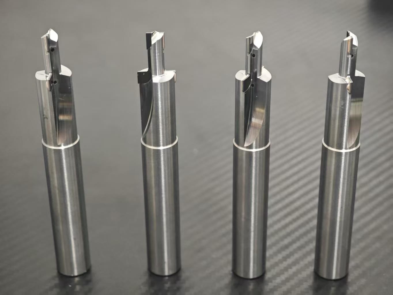
Axial chamfering is simple and repeatable
A center drill, countersink, or combined drill-and-chamfer tool approaches the feature axially. The chamfer width is set mainly by Z depth, tool angle, and the actual hole diameter. On a stable production part with consistent holes, that is straightforward to program and quick to run. A combined tool can also reduce tool changes when drilling and chamfering must stay concentric.
The limitation is equally practical. If the hole diameter changes, the same Z position no longer creates the same chamfer width. Runout, point condition, and uneven entry can also show up directly on the edge. For large chamfers, a conventional countersink may generate chatter because a broad cutting edge enters at once.
Helical chamfer milling adds path control
A helical chamfer mill uses its cutting edges while the machine interpolates around the hole or follows an outside contour. Cutter compensation can adjust the finished width without changing the tool. The same cutter may cover several hole diameters, front edges, back chamfers, or irregular contours if the machine has the required access and simultaneous axis movement.
That flexibility comes with more programming responsibility. Entry and exit should be smooth, and the toolpath must account for cutter diameter, chamfer angle, and radial engagement. Too much engagement can create vibration or a visible witness mark where the tool rolls out of the cut. A long, weak setup can remove the advantage of the milling approach.
Surface condition changes the choice as well. A rough casting edge, interrupted slot, or thin wall may not support a broad axial cut. Chamfer milling can distribute engagement around the path, but only if the cutter reaches the feature without excessive overhang. On a rigid part with hundreds of identical holes, the simpler axial tool may still give the more dependable cycle.
Choose around the part, not the tool name
- Use an axial tool when the hole diameter is stable and cycle simplicity matters.
- Use chamfer milling when several diameters or contour shapes must be covered by one tool.
- Review back-side access before specifying a back-chamfer operation.
- For aluminum or abrasive non-ferrous production, a sharp PCD combined drill and countersink may help control burrs and edge finish.
- For unusual angles, stepped features, or tight concentricity, consider custom tooling rather than forcing a standard cutter.
A useful tooling review starts with the hole diameter, chamfer angle and width, material, tolerance, batch size, machine type, and whether both sides of the edge are accessible. Send those details and a drawing through the Full RFQ form when the chamfer must be controlled as a functional feature rather than simple deburring.