

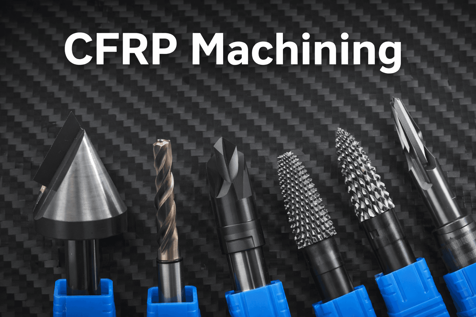
Carbon fiber composite materials are valued for low weight, high specific strength, corrosion resistance, and fatigue performance, which is why they are used in aerospace, automotive, wind power, robotics, and other advanced industrial applications. The same material advantages also make machining more difficult. CFRP is anisotropic, non-homogeneous, and abrasive, so the cutting edge can wear quickly, machining quality becomes harder to stabilize, and the process is more likely to show burrs, edge damage, or delamination if the tool route is not well matched to the material.
This application reference focuses on a sleeve machining job where the target feature is an outer chamfer produced in a turning process. The workpiece is a carbon fiber composite sleeve with a diameter of around 50 mm. The process uses continuous wet cutting, the machining allowance is 0.5 mm, and the roughness target is around Ra 6.3. In this kind of job, the main problem is not only abrasive wear. The insert also has to keep a sharp enough cutting edge to machine the composite structure cleanly without unstable edge quality at the chamfer.
Application snapshot
- Workpiece: Carbon fiber composite sleeve / bushing
- Material: CFRP / carbon fiber composite
- Operation: Outer chamfering in a turning process
- Workpiece size: Around 50 mm diameter
- Coolant: Wet cutting
- Allowance: 0.5 mm
- Surface requirement: Ra 6.3
Previous route vs HEYI reference route
The previous route used a standard carbide insert. For the HEYI reference route, the insert is a custom PCD insert designed for CFRP turning and chamfering, with edge geometry adjusted for the actual machining condition. The purpose of the PCD route is to improve wear resistance while still keeping the sharp edge needed for composite machining.
Reference cutting data includes 0.5 mm depth of cut, 0.005 mm/rev feed, and cutting speed around 251 m/min under wet cutting. In a CFRP turning process, that combination matters because the edge must stay stable under repeated abrasive contact without becoming too blunt to cut the chamfer cleanly.
Result summary
Under the reference condition, the PCD route showed a clear improvement in usable edge life compared with the previous carbide route. The result is best described as more than 10 times longer tool life, together with more stable edge behavior in continuous machining of the chamfer area. That kind of improvement matters when the buyer is trying to reduce frequent insert change, inconsistent edge quality, or unstable process cost on abrasive composite parts.
Why this kind of case matters
Composite machining problems are often treated as a cutting data issue first, but in many CFRP jobs the insert route itself is the more important starting point. If the edge is not designed for abrasive composite behavior, the process can become unstable even when the machine and parameters are acceptable. A custom PCD insert becomes more relevant when the part geometry, edge quality target, or insert life requirement cannot be handled well by a standard carbide route. Buyers comparing possible tooling families can also review the broader PCD Tools range and the current Custom Tooling entry point when the job depends on non-standard edge geometry or application-specific development.
RFQ guidance
For meaningful review, send the sleeve drawing, composite structure, chamfer size, roughness target, machining allowance, coolant condition, current insert life, and the main defect or cost problem in the current process. That information helps HEYI judge whether a standard PCD route is enough or whether the job needs a custom edge design. If your inquiry is already technical and drawing-based, move directly to Full RFQ instead of a general contact request.
If you already have drawing and process data ready, use Full RFQ. If you need a quick first discussion before preparing the full package, use Contact Us. You can also start from the PCD Tools category for related tooling families.